Solar Inverter Isolation Fault (Low Riso / Earth Fault): Causes and Step-by-Step Fix
What an isolation, Riso or PV earth fault on a solar inverter really means, why it shows up on damp mornings, and a safe, systematic way to find the faulty string, connector or module.
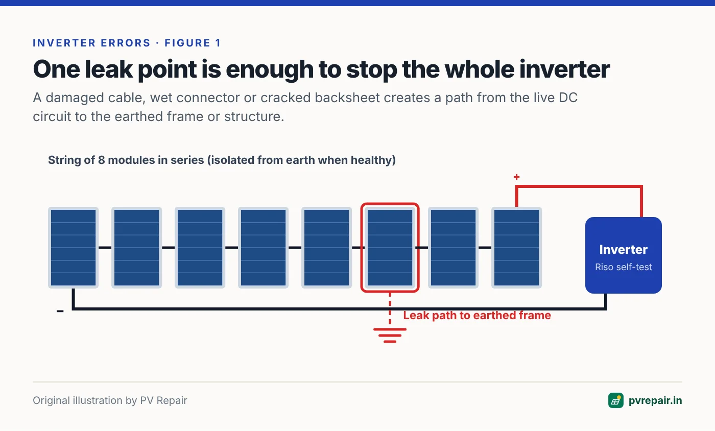
Few inverter alarms cause as much confusion as the isolation fault. Depending on the brand, the screen or app may say Isolation Fault, PV Isolation Low, Riso Low, Insulation Resistance Abnormal, Earth Fault or Ground Fault. They all describe the same thing: the inverter has measured that the DC side of your solar array is leaking current to earth through a path that should not exist.
The fault is a safety function, not a malfunction of the inverter in most cases. A transformerless inverter connects the PV array almost directly to the grid, so the inverter must prove that the array is properly insulated before it closes its grid relays. If the insulation resistance (Riso) between the PV conductors and earth falls below a threshold, it refuses to start. This guide explains why that happens and how to locate the fault without guesswork.
Quick answer
An isolation fault means DC current is leaking from the array to earth. The most common causes are water inside an MC4 connector or junction box, cable insulation damaged by rodents or sharp edges, a module with a cracked backsheet, or a wet DC isolator. The fix is to isolate the array, then test each string's insulation resistance with an insulation tester until you find the one that reads low, and narrow down from there.
What the inverter is actually measuring
Before connecting to the grid each morning, a transformerless inverter measures the resistance from the PV positive and PV negative terminals to protective earth. Internally, this is usually done by switching a known resistor network between the DC bus and earth and calculating the leakage.
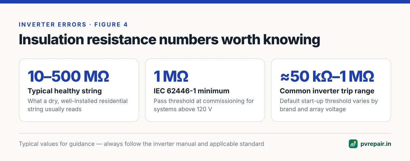
The pass threshold depends on the inverter and the array voltage. Safety standards for PV inverters (IEC 62109-2) require that the leakage current at maximum array voltage is limited, which works out to tens of kilo-ohms as an absolute floor. In practice, most inverters use a default somewhere between about 50 kΩ and 1 MΩ, and some let an installer adjust it within a permitted range.
For comparison, a healthy residential array normally measures in the tens or hundreds of megohms when tested with an insulation tester. A reading in the low hundreds of kilo-ohms is therefore not "a bit low" — it indicates a genuine defect somewhere, even if the system still starts on dry afternoons.
Why it is worse in the morning
Isolation faults are classically intermittent. The inverter fails to start at 6:30 a.m., shows the alarm, and then connects normally by 10:00 a.m. The reason is moisture. Overnight dew and morning humidity soak into any gap in the insulation — a poorly crimped connector, a cracked backsheet, a cable nicked against a rail — and that moisture forms a conductive path. Once the sun dries everything out, the resistance climbs back above the threshold and the inverter connects.
During the monsoon this pattern can turn into an all-day fault. If your inverter generation graph shows a late start on humid days or no generation at all after heavy rain, an insulation problem is the first suspect.
Safety first
An isolation fault means part of your DC system may be live relative to earth. Do not touch module frames, mounting structures or cable trays with bare hands if you suspect a fault, especially in wet conditions. Diagnosis requires an insulation resistance tester, CAT III rated PPE and isolation of the DC side — this is work for a trained technician.
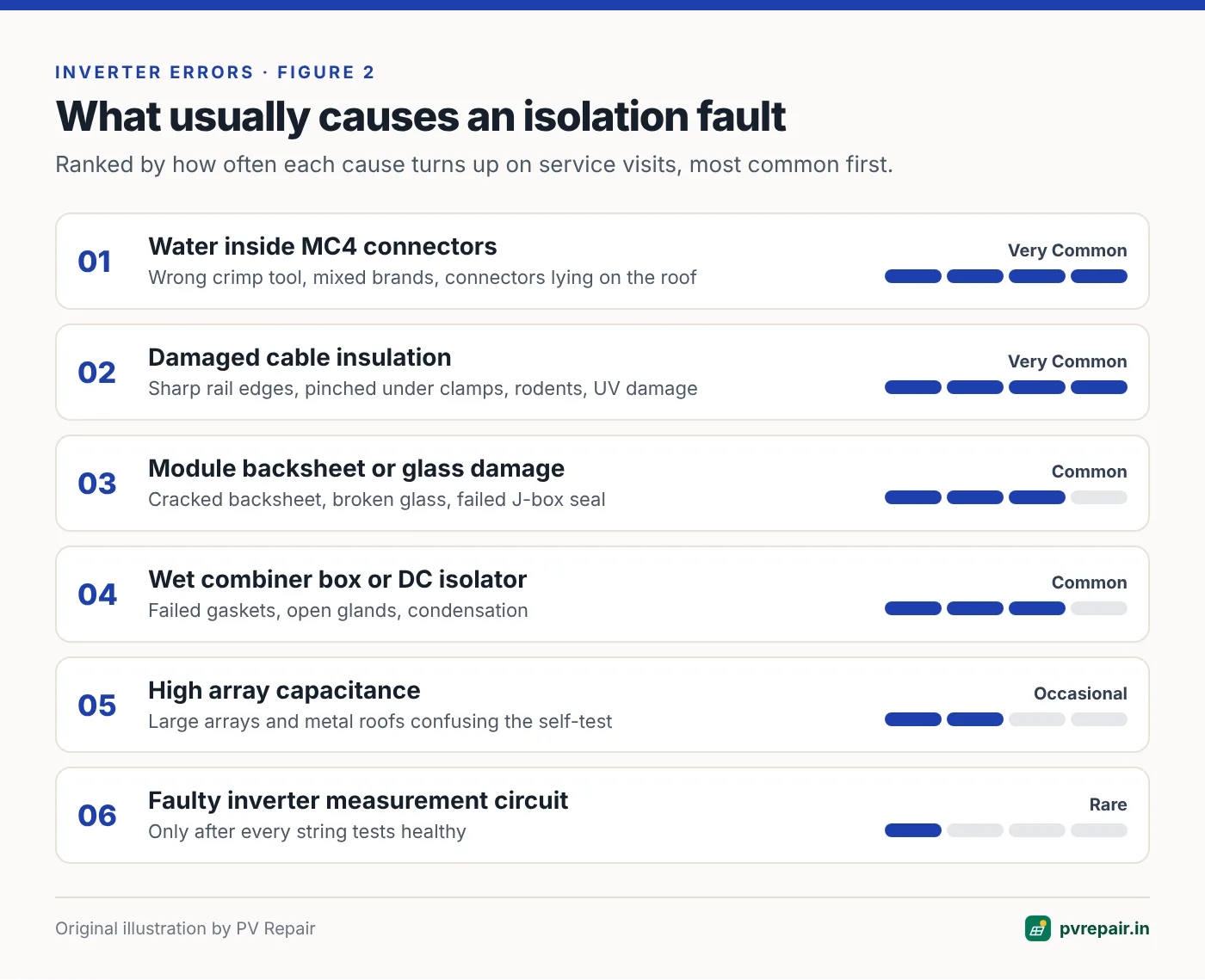
Most common causes, in order of likelihood
Field experience across residential and commercial rooftops shows a fairly consistent ranking:
- Water ingress in MC4 connectors. Hand-crimped connectors without the correct tool, mixed brands that don't seal against each other, or connectors left lying in puddles on the roof are the single biggest cause. See our guide to MC4 connector failures.
- Damaged cable insulation. Cables rubbed against sharp rail edges, pinched under module clamps, chewed by rodents or monkeys, or degraded by UV where they were never rated for outdoor use. Rodent damage is common enough in India that we have a dedicated guide.
- Module defects. A cracked or delaminated backsheet, a broken glass panel, or a junction box that has lost its seal can all leak to the aluminium frame. Read more in delamination, backsheet cracks and broken glass.
- Wet DC combiner boxes or isolators. Enclosures with failed gaskets, open cable glands or condensation inside. Water pooling at the bottom of a DCDB is a frequent find on monsoon service visits.
- Junction box failures. Overheated or burnt junction boxes often end in insulation failure as the plastic chars.
- Large arrays with high capacitance. On big commercial arrays, the sheer area of the array creates a capacitance to earth that some inverters misread at start-up. This is a configuration issue rather than a defect, and is discussed below.
- The inverter itself. Internal measurement circuits do fail, but this is the least likely cause and should only be concluded after the array tests healthy.
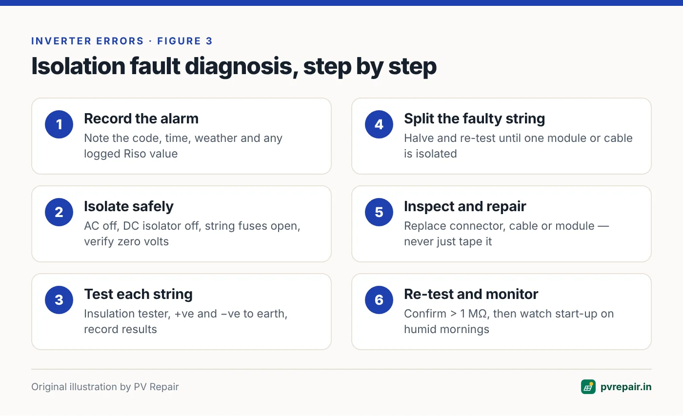
Step-by-step diagnosis
The goal is to find which string — and then which part of that string — has the low insulation resistance. You will need an insulation resistance (IR) tester rated for PV work, a multimeter rated CAT III 1000 V or higher, insulated gloves and the inverter manual.
Step 1: Record what the inverter tells you
Before switching anything off, note the exact error text and code, the time it occurs, and the weather. Many inverters log the measured Riso value in the event log or in the installer menu of the app. A value that varies with humidity points to moisture; a value that stays low on a dry, sunny afternoon points to hard damage.
If the inverter has multiple MPPT inputs, some models report which input has the low reading. That alone can halve your search.
Step 2: Safely isolate the DC side
- Switch off the AC breaker feeding the inverter.
- Switch off the inverter's DC isolator.
- If fitted, open the string fuses or DC isolators in the combiner box.
- Confirm with a meter that there is no voltage on the inverter DC input terminals before disconnecting any connector.
Never disconnect an MC4 connector under load. DC arcs do not self-extinguish the way AC arcs do, and pulling a connector carrying current can cause burns and a fire.
Step 3: Test each string's insulation resistance
With the strings disconnected from the inverter, test each one individually. The method recommended by IEC 62446-1 is to test the positive and negative conductors to earth separately, or to short positive and negative together through a suitable switch and test the combined conductor to earth. Use the test voltage appropriate for the system — for arrays above 120 V, the standard test voltage is 500 V or 1000 V depending on system voltage, with a minimum acceptable result of 1 MΩ.
Record the readings in a table like this:
| String | +ve to earth | –ve to earth | Conditions | Verdict |
|---|---|---|---|---|
| MPPT1-S1 | 180 MΩ | 210 MΩ | 9:15 a.m., humid | Healthy |
| MPPT1-S2 | 0.4 MΩ | 0.6 MΩ | 9:20 a.m., humid | Fault |
| MPPT2-S1 | 95 MΩ | 110 MΩ | 9:25 a.m., humid | Healthy |
Read the position of the fault from the two readings
When a single leak point exists in a string, the ratio between the positive-to-earth and negative-to-earth readings, or the voltage measured from each pole to earth with the string in open circuit, can indicate roughly where along the string the fault lies. If the voltage from negative to earth is about one-third of the string Voc, the leak is roughly one-third of the way along from the negative end. This is a guide, not a precise locator, but it tells you which modules to inspect first.
Step 4: Split the faulty string
Once you know the string, break it into halves at a connector (with the string isolated and in darkness or covered, or at negligible current) and test each half. Repeat until you isolate the fault to a single module or cable run. Inspect each connector you open — moisture, green corrosion or discoloured plastic is a giveaway.
Step 5: Inspect, then repair
When you've narrowed it down, a visual inspection usually reveals the cause: a chewed cable, a cracked backsheet near the junction box, a connector full of water, a cable pinched under a clamp. Repair options:
- Connector: replace both halves with matched, same-brand connectors crimped with the correct tool.
- Cable: replace the damaged run. Taping a PV cable is not an acceptable permanent repair.
- Module: replace it with a compatible module (matching electrical characteristics as closely as possible) and raise a warranty claim if appropriate.
- Enclosure: dry it, replace gaskets and cable glands, add a breather/drain plug and consider relocating it away from water runoff.
Step 6: Re-test and monitor
Repeat the insulation test on the repaired string and record the result. Reconnect, restart the inverter, and watch the start-up time on the next few humid mornings. A system that now starts at first light has been properly fixed.
When the array is healthy but the fault persists
If every string tests above 1 MΩ — ideally on a humid morning when the fault normally appears — consider these possibilities:
- High array capacitance. Large arrays, metal roofs and certain thin-film or frameless modules have a high capacitance to earth. Some inverters misinterpret the charging current as leakage. The manufacturer may advise a firmware update or a different Riso threshold within permitted limits.
- AC-side or earthing issues. A missing or poor protective earth at the inverter, or a neutral-earth problem on the building's AC supply, can confuse the measurement. Check the inverter's earth connection and the earth resistance of the system. Our guide to solar earthing mistakes covers this.
- An internal inverter fault. If the inverter reports the alarm with its DC inputs disconnected entirely (some inverters will start their self-test with only AC present), the internal measuring circuit or a surge protection device inside the inverter may have failed. This is a warranty matter for the manufacturer.
Do not simply lower the threshold
Some installer menus allow the isolation threshold to be reduced. Doing so to "make the error go away" without finding the fault removes an important protection against electric shock and fire. Only change the setting where the manufacturer explicitly advises it for a verified healthy array.
How to prevent isolation faults
Prevention is mostly about installation quality:
- Use one brand of connector throughout and crimp with that manufacturer's tool.
- Keep connectors off the roof surface and out of places where water collects.
- Route cables in UV-resistant conduit or covered cable trays, and protect against rodents.
- Fit edge protection where cables pass over rails or sheet metal.
- Choose combiner boxes rated at least IP65, with glands sized for the cable and a drain or breather.
- Include an insulation resistance test in your annual maintenance checklist and keep the results so you can see a decline before it becomes a fault.
Frequently Asked Questions
Can I keep using my solar system with an isolation fault?
The inverter will usually refuse to connect while the fault is present, so it protects you by stopping generation. When it starts again on a dry afternoon, the underlying defect is still there and will usually worsen. Get it diagnosed soon, especially before the monsoon.
Is an isolation fault the inverter's fault?
Rarely. In the large majority of cases the inverter is correctly detecting a real insulation problem on the DC side. Only conclude the inverter is faulty after every string tests healthy with an insulation tester.
What is a normal insulation resistance reading for a solar array?
A healthy string typically reads well into the tens or hundreds of megohms. IEC 62446-1 sets a minimum of 1 MΩ for systems above 120 V. Readings close to that minimum on a new system are a warning sign.
Why does the error only appear after rain?
Water bridges small gaps in insulation — inside connectors, along a scratched cable or through a cracked backsheet. When everything dries out the resistance rises again and the inverter starts. The pattern strongly suggests moisture ingress at a specific point.
Can a single bad solar panel cause an isolation fault?
Yes. A module with a cracked backsheet, failed junction box seal or broken glass can leak to its frame, which is earthed. One faulty module is enough to stop the whole inverter.
Related guides
PV Overvoltage Error: When String Voltage Exceeds Your Inverter's Limit
Why PV overvoltage alarms appear on cold, bright mornings, how to calculate maximum string voltage with temperature correction, and how to fix an oversized string before it damages the inverter.
How to Read Solar Inverter Fault Codes: A Universal Guide for Any Brand
Inverter error codes look cryptic, but almost every brand groups them into the same handful of categories. Learn to decode any fault code, use the event log, and decide what you can check yourself.
Solar Inverter Not Turning On? A Systematic Diagnosis From Panels to Display
Blank screen, no LEDs or stuck on "Waiting"? Work through the DC supply, start-up voltage, isolators, fuses and internal faults in the right order to find why your solar inverter won't start.